AVR digital comb filter (humnuller)
This project is a digital comb filter built with an ATmega168. The purpose of this filter is to clean a realtime audio signal, removing the ubiquitous 60Hz (50Hz in some countries) noise caused by power lines and household electrical wiring. Since the noise is not strictly sinusoidal it is necessary to remove all harmonics of 60Hz, and that is what this filter does.
The cleaning algorithm works by building a sort of average background waveform and then subtracting this from the signal to pick out only the non-periodic features. The result is that signals that oscillate at 60Hz or multiples thereof get attenuated while everything else passes through unchanged. The bandwidth is limited to 24kHz due to both RAM and CPU constraints in the ATmega168 chip. As a workaround it is possible to use the digital filter to just output the simulated background waveform and subtract this from the signal using an analog circuit. This mode can be selected by tying pin PD6 to ground, however if you really want to go this route it may be necessary to make some modifications to the code to avoid phase shift.
Residential power isn't tuned to exactly 60Hz, it drifts higher and lower. To account for this we use an autocorrelation function to lock on to the signal. This also counteracts inaccuracies in the AVR's clock (ceramic resonators have about a 0.5% tolerance). Before the system can be used an initial calibration needs to be done. To do this, tie PD4 to ground before applying power to the AVR. Wait for the filter to lock on to the signal and then remove the tie from PD4 to ground. This will write a clock calibration parameter to EEPROM which will be used to initialize the sampling rate whenever the filter is powered up.
As an extra bonus feature, both the source and the filtered waveforms will be output via the serial port when PD3 is not tied to ground. If you are running Linux and have a serial port capable of a 2M baud connection (an FTDI-USB cable will do) then you can use the included oscilloscope program to view these waveforms on your computer. The oscilloscope (ab)uses gnuplot to animate the traces in realtime so you will need a fast computer (I think that gnuplot wasn't really meant for this kind of realtime animation).
The included schematic shows an implementation that takes 9 volts power and a 9 volt audio signal, and sends output to a speaker using an LM386 amplifier. I will use this for a general-purpose amplifier that can be used to listen to signals from an inductive pickup, E-field sensor, or photodiode. All three of those inputs require removal of a significant amount of 60Hz noise (or the 120Hz harmonic in the case of the photodiode).
There is a define in the source code that can be used to select between a base frequency of 50Hz or 60Hz. Set this to the power line frequency for your country.
| Pin | Label | Function |
|---|---|---|
| 4 | PD2 | 1=band gap filter, 0=band pass filter |
| 5 | PD3 | disable uart when tied low |
| 6 | PD4 | activate calibration when tied low |
| 12 | PD6 | PWM waveform output |
| 23 | ADC0 (PC0) | waveform input |
| 15 | PB1 | clip indicator |
| 16-19 | PB2-PB5 | correlation indicators |
| 21 | AREF | connected to voltage divider |
- The schematics and source code
- Karen's PIC humnuller
- A hum filter that runs on a PC
- ULF receviers - these could make use of a hum filter
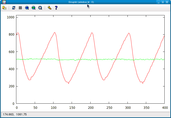
Red: input from photodiode, Green: signal with the 60Hz harmonics removed
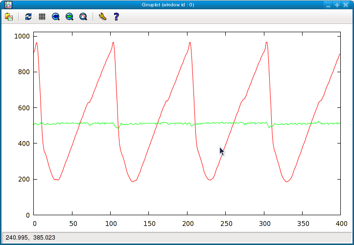
Same as above, but with a florescent lamp shining on the sensor. Here
there is a very steep slope to the curve that is hard to filter out. A
little bit of this makes its way to the output. Since residential power
frequency drifts the input falls out of alignment of the averaged
background waveform.